Selective Laser Sintering (SLS) offers exceptional design freedom. Parts can be printed without support structures, enabling internal channels, complex geometries, and moving assemblies in a single build. But freedom does not mean anything goes.
To get reliable, functional parts from an SLS printer, you need to follow specific design guidelines. This guide covers four critical design areas: wall thickness, hole diameter, dimensional tolerances, and living hinges. Each section includes recommended values, practical tips, and trade-offs to consider.
Whether you are designing functional prototypes or production parts, these guidelines will help you avoid common failures and achieve consistent results.
Wall Thickness Guidelines for SLS
Wall thickness is one of the most important design decisions in SLS printing. Walls that are too thin may break during post-processing or fail in use. Walls that are too thick waste material, increase print time, and can cause warping due to uneven cooling.
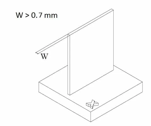
Recommended Minimum Wall Thickness
For reliable, repeatable results with SLS nylon (PA12), the recommended minimum wall thickness is 0.7 mm to 1.0 mm . Features under 0.7 mm are considered “best effort” and may not resolve consistently or could be too fragile to withstand post-processing like bead blasting .
Detailed guidance by material:
| Material | Minimum Wall Thickness | Recommended Range |
| PA12 Nylon | 0.7 mm | 1.0 – 1.2 mm |
| Glass-filled PA12 | 0.8 – 1.0 mm | 1.2 – 1.5 mm |
| Carbon-fiber filled PA12 | 1.0 – 1.5 mm | 1.5 – 2.0 mm |
| TPU (flexible) | 1.2 mm | 2.0 mm |
Note: Living hinges can be printed at 0.3 mm thickness, which will be covered later in this guide.
Thin Walls: What Works in Practice
Real-world testing on SLS systems demonstrates that 0.5 mm walls are printable and accurate. In a recent test on the TPM3D P360, a 0.50 mm wall printed with only a +0.02 mm deviation . This shows that SLS can handle thin features, but reliability decreases as wall thickness approaches the lower limit.
Key considerations for thin walls:
Avoid walls thinner than 0.5 mm — they can collapse during printing or fail during powder removal. Laser heating can also cause walls under 0.5 mm to overheat and thicken .
Add ribs for support — large flat surfaces are prone to warping. Including ribs in your design adds structural support without significantly increasing weight .
Design for uniform wall thickness — sudden changes in wall thickness create stress concentration points. Gradual transitions help distribute stress and reduce warping.
Wall Thickness and Part Function
Thicker walls increase strength and stiffness. Thinner walls reduce weight and material cost. The right choice depends on your application.
| Application | Recommended Wall Thickness | Reasoning |
| Visual prototypes | 0.8 – 1.2 mm | Lightweight, minimal material use |
| Functional parts | 1.2 – 2.0 mm | Strength and durability |
| Structural brackets | 2.0 – 4.0 mm | Load-bearing applications |
| Living hinges | 0.3 mm | Flexibility required |
Hole Diameter and Internal Features
SLS can print holes and internal channels directly, eliminating the need for post-machining. However, there are limits to what is possible.
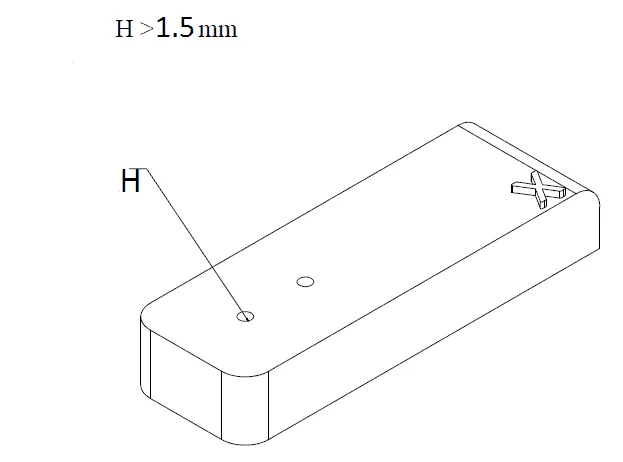
Minimum Hole Diameter
The recommended minimum hole diameter for SLS is 1.0 mm to 1.5 mm . Holes smaller than this may be difficult to clean and can trap unsintered powder. Additionally, very small holes are more likely to be affected by thermal expansion during printing.
Guidance for holes:
Minimum diameter: 1.0 mm — Features below this are considered “best effort” .
Recommended minimum: 1.5 mm — Reliable and cleanable with standard post-processing .
Escape Holes for Powder Removal
| Feature | Recommended Size | Notes |
| Powder removal | 3.5 – 5.0 mm | 5 mm is “best effort”; larger is better for complete removal |
| Media tumbling | 5.0 mm+ | For internal polishing through tumbling |
| Internal channels | As large as possible | Consider post-processing access |
Design tip: If a hollow part must be sealed, consider alternative approaches. Fully enclosed cavities trap powder and can cause problems during use .
Tolerances and Dimensional Accuracy
SLS parts achieve excellent dimensional accuracy, but tolerance is not a fixed number. It depends on part size, geometry, and material.
Standard Tolerances
The general tolerance for SLS is ±0.3% of the part dimension, with a minimum of ±0.3 mm .
| Part Size | Tolerance |
| Under 100 mm | ±0.3 mm |
| Over 100 mm | ±0.3% of dimension (e.g., ±0.6 mm for 200 mm) |
What This Means in Practice
In real-world testing, SLS systems hold tight tolerances. For parts in the 18–35 mm range, measured deviations are typically under ±0.05 mm on horizontal (XY) dimensions .
Key observations from real part measurements :
XY (horizontal) accuracy is excellent — often under ±0.05 mm for small to medium parts
Z (vertical) accuracy is slightly lower — vertical deviations are typically larger due to layer-based processing
Positive bias — parts often print marginally larger than the CAD design, which can be compensated for if needed
Factors That Affect Tolerances
Several factors influence SLS dimensional accuracy :
| Factor | Impact | Mitigation |
| Material shrinkage | PA12 shrinks roughly 3% during cooling | Account for in design; predictable with stable materials |
| Part geometry | Large, flat areas prone to warping | Use uniform wall thickness and ribs |
| Build orientation | Affects thermal stress and accuracy | Balance precision with build efficiency |
When to Use Post-Machining
If a critical feature requires tighter tolerances than SLS can provide (e.g., a bearing bore), design the part with extra material so it can be drilled, reamed, or milled in a secondary operation .
Living Hinges in SLS
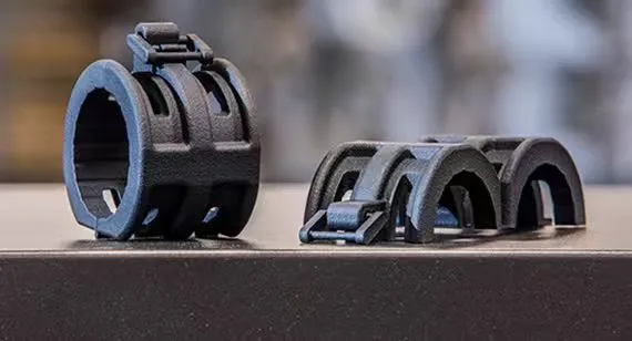
SLS is the preferred 3D printing technology for living hinges because it uses nylon thermoplastics (PA12 and PA11) with the elongation and fatigue resistance needed for repeated flexing . Living hinges that bend and flex repeatedly are possible with SLS — but only with careful design.
Material Selection
For living hinges, material choice is critical:
| Material | Suitability for Living Hinges |
| PA11 (Nylon 11) | Best — highest elongation at break (14-51%) |
| PA12 (Nylon 12) | Good — elongation at break (24%) |
| Glass-filled or carbon-filled nylons | Avoid — too stiff, will snap rather than bend |
| TPU | Possible but rarely appropriate for the rest of the geometry |
Hinge Dimensions
Unlike injection-molded living hinges (which can be as thin as 0.013 inches), SLS hinges need more substantial geometry .
Recommended dimensions for SLS living hinges :
| Parameter | Recommended Value |
| Thickness | 0.3 – 0.5 mm (0.012 – 0.020 in) |
| Length (for 90° bend) | Minimum 1.27 mm (0.050 in) |
| Length (for 180° bend) | Minimum 3.81 mm (0.150 in) |
| Minimum clearance between moving parts | 0.5 – 0.6 mm |
Design principle: The hinge needs to be the weakest part of the assembly. If the hinge is as thick as the surrounding geometry, the part will distort when flexing instead of bending at the hinge .
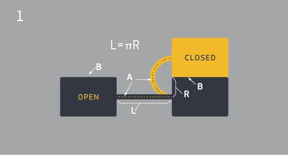
The Hinge Length Formula
The ideal relationship between hinge length and placement follows the formula L = πR (where L is hinge length and R is the bend radius). This allows the hinge to form a semicircle when in the closed position, evenly distributing stress along the hinge .
What happens when the formula is not followed:
L < πR: Stress is concentrated at attachment points; hinge will be under tension
L > πR: Stress concentrates at attachment points and the middle; excess material acts as a spring, prying apart mating surfaces
Post-Processing for Living Hinges
A living hinge printed in nylon will not function immediately after printing. Post-processing is essential.
Recommended process :
Heat the part to 250-275°F
Flex the hinge through its intended range of motion while hot
Allow to cool in the flexed position
This step aligns polymer chains and extends hinge life by stretching the material rather than fracturing the links between polymer chains. With proper design and post-processing, SLS living hinges can withstand hundreds of flex cycles .
Additional Design Considerations for SLS
Clearance Between Moving Parts
For assemblies printed as a single piece, allow sufficient clearance between moving or interlocking parts:
| Clearance Type | Recommended Minimum |
| Between assembled parts | 0.5 mm |
| Between moving/connecting parts | 0.6 mm |
| Interlocking features | 0.5 – 1.0 mm |
Minimum Feature Size and Text
For fine details and readable text:
| Feature | Recommended Minimum |
| Minimum detail (embossed features)0.7 mm | 0.7 mm (features under 1 mm are “best effort”) |
| Text height | 2.0 mm |
| Text depth | 1.0 mm |
| Font style | Sans serif (easier to read and print) |
Avoiding Warping
Large, flat surfaces are susceptible to warping in SLS because of uneven cooling and internal stress .
How to reduce warping risk:
Avoid large flat areas where possible
Use ribs to support flat surfaces
Design with uniform wall thickness throughout the part
Frequently Asked Questions
What is the minimum wall thickness for SLS?
The recommended minimum wall thickness for reliable results is 0.7 mm to 1.0 mm for PA12 nylon. Living hinges can be as thin as 0.3 mm.
How accurate are SLS-printed parts?
General tolerance is ±0.3% of the part dimension, minimum ±0.3 mm. For parts under 100 mm, expect ±0.3 mm. For parts over 100 mm, tolerance scales with size .
What is the smallest hole I can print in SLS?
The recommended minimum hole diameter is 1.0 mm to 1.5 mm. For powder removal, escape holes should be at least 3.5 mm .
Can SLS print living hinges?
Yes. SLS is the preferred technology for 3D-printed living hinges. Use PA11 or PA12 nylon, design with 0.3-0.5 mm thickness, and post-process by heating and flexing the hinge to extend its life .
Do I need support structures for SLS?
No. SLS is a support-free process. The unsintered powder bed supports the part during printing, enabling complex geometries and internal features without support removal.
Conclusion
SLS 3D printing offers exceptional design freedom, but success depends on following proven design guidelines.
Key takeaways:
Wall thickness: 0.7-1.0 mm minimum for reliable results; 0.5 mm is possible but at risk
Holes: Minimum 1.0-1.5 mm; use 3.5 mm+ escape holes for powder removal
Tolerances: ±0.3% (minimum ±0.3 mm); plan for post-machining on critical features
Living hinges: 0.3-0.5 mm thickness; use PA11 or PA12; post-process with heat and flexing
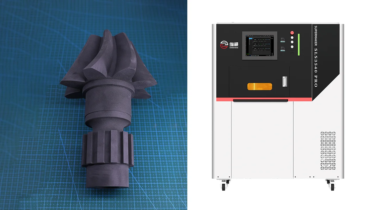
The Zongheng3D SLS3540 Pro offers the precision and build volume needed for demanding SLS applications. With its 350 x 350 x 400 mm build capacity and ±0.15 mm accuracy, it can handle both prototyping and production runs with consistent quality.